Learn about Li-ion Battery for Electric Vehicle – Part-1

Learn about Li-ion Battery for Electric Vehicle – Part-1

Learn about Lithium-ion Battery for Electric Vehicle – Part-1

Let us start with the basics of Lithium-ion Battery for electric vehicles. Next, we will deal with the metal Lithium, Raw Materials for Li-ion battery, Structure of the fundamental Li-ion battery cell and The Working principle of the li-ion battery.

1.0: Some notes about metal lithium

To start with let’s have some ideas about the metal Lithium. Lithium is an element discovered by Johan August Arfvedson in 1817. The name is derived from the Greek “lithos” meaning stone. The chemical symbol is “Li” and atomic number is 3. It is soft and silvery white alkali metal. Lithium is highly reactive and flammable. Lithium is the 35th most abundant element on earth. Earth has a stock of approximately 230 billion tons of lithium. Lithium is available in ocean water and commonly extracted from brines. The largest Lithium sources in the world are Chile and Australia and US, Argentina and China are also some of the major producers.

Lithium Stock in world.

Fig_1: Lithium from Brines

Fig_1A below shows Lithium-ion world production as predicted up to the year 2020.

Lithium Ion World Production.

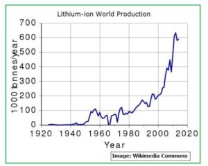
Fig_1A: Lithium-Ion world production

 Commercial Lithium is recovered by evaporating brines collected from salars and salt lakes in evaporation ponds. It takes a year or more to recover Lithium this way and leaves behind lots of salt waste. There are the latest technologies and processes that offer more profitable options for Lithium extraction. 

Lithium is sometimes precipitated as Lithium Phosphate for faster precipitation and then Lithium Phosphate is converted into battery-grade Lithium Hydroxide through an electrochemical process.

1.1: Are Lithium-Ion battery used in electric vehicles different from conventional gas-powered vehicles?

Electric-vehicle batteries are different from gasoline-based automobiles which use SLI Batteries (Starting, Lighting, and Ignition). The Electric Vehicle batteries are designed to give power over prolonged periods of time so that the vehicle can run a long distance without recharge. Deep-cycle high ampere-hour capacity batteries are used instead of SLI batteries for EV applications.

The battery in an electric vehicle must deliver power to drive the electric motor. Electric Vehicle batteries are a secondary (rechargeable) battery.

Lithium-ion batteries are used in Electric Vehicles due to their high energy density, high power density, long lifespan and environmental friendliness.

These batteries are excellent for energy storage solutions.

We will now peep inside the Lithium-ion battery specifically manufactured for electric vehicles to find out their typical raw materials requirements and internal structures

1.2: Lithium-ion Battery Raw Materials:

Fig_2 below has details of all the metals which are used to make lithium-ion battery. Some of them are used to make the Anode and most are used to manufacture Cathode. Apart from Lithium, the most used metals are Nickel, Cobalt and Aluminum.

Raw Materials used to make Li-ion Battery

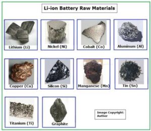
Fig_2: Raw Materials used to make Li-ion Battery

 1.3: Structure of a typical Lithium-ion Battery Cell:

Fig_3 below shows the internal structure of a typical Lithium-ion battery cell.

Figure shows the Structure of a Lithium Cell

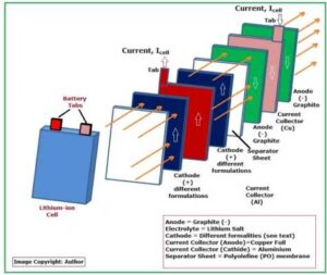
Fig_3: Structure of a Lithium Cell

Each lithium-ion cell contains THREE major parts:

  1. Anode (Graphite) negative electrode
  1. Electrolyte (Lithium Salt)
  1. Cathode (Differently Formulated – positive electrode)

Apart from these 3 items, there are Current Collectors, Separator sheets and cover for the cell. Here are the details of all these parts:

1.4: About Current Collectors:

Typically, Copper Foil is used as the negative electrode, or the anode current collectors and aluminum is used as the positive electrode or the cathode current collectors.Aluminum oxidizes more easily than copper to form metal oxide for electrochemical oxidation. Aluminum is also prone to galvanic corrosion in contact with copper.

In fact, aluminum oxide film forms on the aluminum base metal. Aluminum oxide is known to be chemically and electrochemically a stable film. Therefore, the oxide film of the aluminum can be considered as the auxiliary (cathode) electrode in Li-ion battery, in which the exchange current is very high compared to the copper at the anode side. The net exchange current of the aluminum oxide is equal to zero.   In other words, the aluminum oxide film doesn’t polarize. This is the reason which makes aluminum oxide film an excellent current collector.

A rolled foil (RA-type), made from wrought Cu is generally used for Li-ion battery used for electric vehicles as the requirement is high-energy and high-power. Aluminum foils are used as the cathode current collector of secondary Li-ion batteries. Currently, the anode is comprised of a Graphite mixture, while the cathode combines Lithium and other choice metals, and all materials in a battery have a theoretical energy density. With Lithium-ion, the anode is well optimized, and design changes will yield little to no significant improvements in performance. On the other hand, the cathode material is wide open to enhancements and explains why today’s battery research is so heavily focused on this area.

Cathode Active Materials:

Cathode Active Materials are the main elements having different compositions which are the basic requirements for manufacturing positive electrodes for battery cells. The cathode materials are comprised of cobalt, nickel and manganese in the crystal structure forming a multi-metal oxide material to which lithium is added. The batteries manufactured specifically for electric vehicles use a variety of Cathode materials to cater to different application requirements for high energy density and high load capacity.

5 types of Cathode materials are used to manufacture Lithium-ion batteries for electric vehicles:

  1. NMC (NCM) – Lithium Nickel Cobalt Manganese Oxide (LiNiCoMnO2) – 29%
  1. LCO – Lithium Cobalt Oxide (LiCoO2) – 26%
  1. LFP – Lithium Iron Phosphate (LiFePO4) – 23%
  1. LMO – Lithium Manganese Oxide (LiMn2O4) – 12%
  1. NCA – Lithium Nickel Cobalt Aluminum Oxide (LiNiCoAlO2)- 10% 

Apart from Lithium, some other metals are also used to manufacture Cathode. In fact, there are many varieties of Cathodes with different formulations.

Fig_3A Tabulates the formulations used in some of the major ones.

Figure shows the Chemistry of Cathodes in Lithium-Ion Cell.

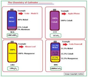
Fig_3A: The Chemistry of Cathodes

About Separator Materials:

The safety of a li-ion battery cell is dependent on the separator. This is a thin, porous membrane which separates the cell cathode and anode. The separator prevents physical contact between cathode and anode. The challenge is to manufacture a separator which will be mechanically strong and at the same time porous to facilitate transport properties. Separators are normally manufactured out of simple plastic films that have the right pore size to allow ions to flow through and block the other components. Polypropylene (PP), Polyethylene (PE), and ceramic-embedded battery separators is found to have the required porosity, lightness and durability.

1.5: Li-ion Battery working principle: 

We have explained above that the primary components of Li-ion batteries are Anode, Cathode and Separator.

Li-ions intercalate and de-intercalate between the anode and cathode during charging and discharging process. Intercalation in Li-on batteries will take place only during the charging and discharging process and not when the battery is idle or when the battery is dead. A Li-on battery, like all batteries, consists of a positive electrode, negative electrode, and electrolytes. During discharging, the positive Lithium ion moves from the negative electrode (usually graphite) and enters the positive electrode (usually lithium oxide) through the electrolyte solution (made of organic solvent in solid or liquid form). During charging, the opposite of this process occurs, which is the reason why this is known as a reversible process.

This is clearly shown in Fig_4 below:

Schematic of Li-ion battery working principle 

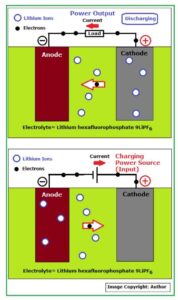
Fig_4: Schematic of Li-ion battery working principle

 During charge / discharge procedure, a chemical reaction caused by or accompanied by an electrical current (electron flow) takes place as shown in the above figure.

The basic functions of the three components in a Li-ion battery are as below:

  1. The Anode or negative electrode: This is the reducing or fuel electrode which releases electrons to the external circuit and oxidizes during the electrochemical reaction. 
  1. The Cathode or positive electrode: This is the oxidizing electrode which accepts electrons from the external circuit and reduces during the electrochemical reaction. 
  1. The electrolyte is the ionic conductor: This provides the medium for transfer of charge, as ions, inside the cell between the anode and cathode. The electrolyte is typically a liquid, such as water or other solvents, with dissolved salts, acids, or alkalis to improve ionic conductivity. Some batteries use solid electrolytes, which are ionic conductors at the cell operating temperature. 

Part-2 of this Series will have more knowledge-based details about Lithium-Ion Battery used in Electric Vehicle.

Click to manufacture 7.4kW AC EV Charger.

 Click to get Classic Overlay for your Products


Pilot Wire Communication and Controls in Type 2 EV Charger

Pilot Wire Communication and Controls in Type 2 EV Charger

Pilot Wire Communication is most important for secured operation of AC EV Chargers.

1.0: Introduction:  EV Charging technology is quite advanced as Electric Vehicle in the current form is quite new. This technology is basically used to charge Electric Vehicle Batteries. It’s highly important to take care of the Safety factors of  Battery during charging as any irregularities can cause the batteries to catch fire. Lithium-ion battery cells combine a flammable electrolyte with significant stored energy, and if a lithium-ion battery cell creates more heat than it can effectively disperse, it can lead to a rapid uncontrolled release of heat energy, known as ‘thermal runaway’, that can result in a fire or explosion.


1.1: The EV Charging technology takes care of the safety of the Li-Ion Battery and provides safe & user-friendly charging of the EV Batteries through effective pilot wire communication. To understand it better, we have to understand the difference between “communication” and ‘controls’ in EV Charging. In EV Charging, the EVSE (the charger) communicates some of its important parameters to the Electric Vehicle before and during the charging process. EVSE never controls anything in an electric vehicle during charging.


 In case of AC charging, the EVSE will communicate with the EV through pilot wire communication and when permitted by the EV, it will just deliver the required AC Power to the “On-Board Charger” of the EV. Charging start, charging operation and charging stop will be completely controlled by the EV. The EVSE will not control anything of “On-Board Charger” of the EV. However, EVSE can STOP Charging in case of any problem.


1.2: Let’s see how EV Chargers normally charges an electric vehicle?


www.elecdesignhub.com_pilot wire communication

If you see Fig-1 closely, you’ll be able to find out how AC & DC Chargers will function.

All electric vehicles are manufactured with a built-in “On-Board Charger”.

The AC Charger connector is Type 2 (often referred to as Mennekes – Company that designed it).


1.3: Let’s find out Type 2 Connectors Pinout and relevant details:

Type 2 Connector is a 7 Pin Connector. Male Socket will be built-in Electric Vehicle and Female Plug will be in the Charger with trailing cable (See Fig-1A below).


www.elecdesignhub.com_type 2 socket pin configuration

Fig – 1A


www.elecdesignhub.com_pilot wire communication

Fig – 1B


www.elecdesignhub.com_pilot wire communication

Fig – 1C

Fig-1C above describes the function of each pin in Type 2 Connector.

Out of 7 Pins 3 Pins – PP, PE & CP are used to establish digital communication between charger and EV and the other 4 Pins – N, L1, L2 , L3 are used to transfer AC Charging power to the EV.

PE is panel earth and connected to GND (- common) of 12V SMPS or in other words PE acts as the reference pin for CP & PE.


The DC 12V SMPS supplies power to all cards.


1.4: The On-Board Chargers are built to accept AC Power at the input which will be converted to suitable DC Power to charge the Li-Ion Battery of the electric vehicle. To restrict weight increment of the electric vehicle, the On-Board Chargers have a limited maximum capacity of 22kW (32A maximum current capacity). As the name implies, AC Chargers delivers AC voltages to the On-Board Charger and so the AC Charger capacity can be maximum 7.4kW in 230V Single Phase AC and 22kW (7.4 X 3) in 230V Three Phase AC.


1.5: EVSE communicates the following parameters to EV: (1) Maximum available current during charging and this is communicated to EV before the charging could actually begin and also throughout the charging process. AC Charger performs a handshake with the EV before charging and this communication is called the pilot wire communication. The communication is done through PWM signal which is generated by the EVSE. The specification of the PWM is standardized and quite inflexible. PWM Pilot Wire Communication: Frequency = 1kHz +/- 0.1% Duty Cycle = Maximum Current Capacity / 0.6 +/- 0.1% You can see that the tolerance is very tight and has to be strictly maintained by the EVSE. But why the tolerance is so tight? This question can be answered only when we will go through the charging process:


1.6: Let’s see an actual AC Charging process:


STEP-1: Plug & Socket Not Engaged

www.elecdesignhub.com_pilot wire communication


Fig-2 above is an equivalent circuit drawn to understand the theory behind electric vehicle charging. 

In Fig-2, the Left Block is the Charger or EVSE equivalent circuit and the right block is the Vehicle or EV equivalent circuit.

The Pilot Wire communication is performed by 3 connections – PP, PE & CP of the Type 2 Plug & Socket.

PE is connected to Earth of EVSE. PE of EV cannot be connected to Earth as it stands on insulated tires and so EV gets the Earth connection through EVSE when Plug is engaged.

PP is the proximity pin. The EV PE pin is connected to Earth (GND) via a resistor Rc. The value of Rc is standardized as per EVSE Current capacity (shown below).


www.elecdesignhub.com_pilot wire communication


CP is the control pilot pin through which EVSE and EV Pilot Wire Communication is performed.

The left hand block of EVSE has a hardware controlled switch S1.

The right hand block of EV has a hardware controlled switch S2.

The red square block is the equivalent Load that EV will control through CP pin as and when required. When switch S2 is open, the equivalent load will be 2.74k Ohms and when Switch S2 is closed, the equivalent load will be reduced to 882 Ohms.


STEP-2: PWM – Pilot Control – Plug & Socket Engaged

The System is initialized & EV will check whether Plug is Engaged properly through Rc.

www.elecdesignhub.com_pilot wire communication


Now, PP of EV is connected to Earth (GND) of EVSE through Rc. PE & CP of both EV & EVSE are connected.

In STEP-1, the voltage at CP pin of EVSE was +12V DC as Plug was not engaged.

When Plug is engaged in STEP-2, CP of EVSE will be connected to GND through 2.74k Ohms and this will reduce the Voltage at CP of EVSE to +9V DC. The EVSE will measure this voltage and understand that the Plug is engaged.


But, how the EV will know that the Plug is properly engaged or not?

Well, EV will send a small current through Rc and measure the voltage drop across Rc to find out that the Plug is properly engaged. Rc serves a dual purpose, it ensures that plug is properly engaged and when EV will measure the value, it will also know approximately the range of maximum current capacity of the charger (See Chart-1).


STEP-3: PWM – Pilot Control – Plug & Socket engaged.


Charger will make S1 ON and PWM Signal will be transmitted to EV.


www.elecdesignhub.com_pilot wire communication


As soon as the Charger finds that voltage at CP is +9V DC, it will understand that the Plug is properly engaged and Put on the Switch S1 to transmit PWM Signal to the EV. The EV will read this PWM Signal to find out the Maximum Charging Current Capacity of the Charger. The EVSE has to generate accurate PWM signal transmission to EV. Here’s the Standard:

www.elecdesignhub.com_pilot wire communication


Duty Cycle of PWM Pulse is measured % , here is a simple formula to find the Duty Cycle:

Duty Cycle = Maximum Current / 0.6 Example = Duty Cycle for 32A Current = 32/0.6= 53.3%

EV will read the received PWM Signal to find out whether it’s compatible to its own “On-Board Charger”.


Let’s take an example to understand these criteria:

Say, the EVSE sends a PWM Signal of Frequency 1kHz @53.3% Duty Cycle. This means the EVSE can transfer a charging current of maximum 32A and not more (See Chart-2).


Now, the EV will find out whether its “On-Board Charger” is compatible to 32A or not.

If it is compatible, then the EV will take the next Step in charging.


1.7: Now here is an important feature of EV Charging: The EV can use the available 32A or anything less than that, but never more than 32A as the EVSE will trip at 32A Maximum current.


1.8: The EV charges its Battery through “On-Board Charger” and the algorithm is CC-CV as shown below (Chart-3):


www.elecdesignhub.com_pilot wire communication


This CC-CV Charging algorithm is a built-in feature of the “On-Board Charger” and not controlled by the EVSE. The “On-Board Charger” will reduce the current when Constant Voltage stage will arrive. So, the EV decides how much current to draw from EVSE subject to the Maximum Current capacity of the EVSE.


“EVSE will never control the current, it will only communicate to the EV through PWM signal by Pilot Wire Communication the Maximum Current Capacity.”


www.elecdesignhub.com_pilot wire communication


The EV will read the PWM Signal and if it’s compatible to its “On Board Charger”, it will make Switch S2 – ON. As soon as S2 is ON, the load at CP will reduce to 882 Ohms. This will reduce the Voltage at CP to +6V DC. The EVSE will read the voltage and understand that EV has given permission to start the charging process. So, EVSE will connect the AC Voltage to the EV and Charging will start.


The “On Board Charger” of EV will carry out the charging through CC-CV method. This means that the charging is entirely controlled by the EV only. As soon as the charging is over, EV will open S2 and the Voltage at CP of EVSE will become +9V DC again. EVSE will understand that charging is completed and it will provide a ‘Charge Complete” signal to the user. The user will now release the Charging Plug to detach the EV from EVSE.


If the PWM Signal transmitted by the EVSE fluctuates more than the allowable tolerances, then EV will STOP Charging and wait for the PWM to stabilize or if it’s not stabilized within 30 seconds, it will abort charging.

So, in practice, you have to generate a stable PWM Signal within the allowable tolerances and this is definitely a tough job. This is the only problem faced by many EV Charger manufacturers. You may click the following link to find out how “Elec Design Hub” has used ESP32 to generate a highly steady and accurate PWM Signal for Pilot Wire Communication.


Click:  Home EV Charger – 7.4kW-Type 2 Complete Design Package

 Click here to get your EV Charger Front Panel Overlay design: