We’ll Provide a Complete Solution for your Project Thesis Design.
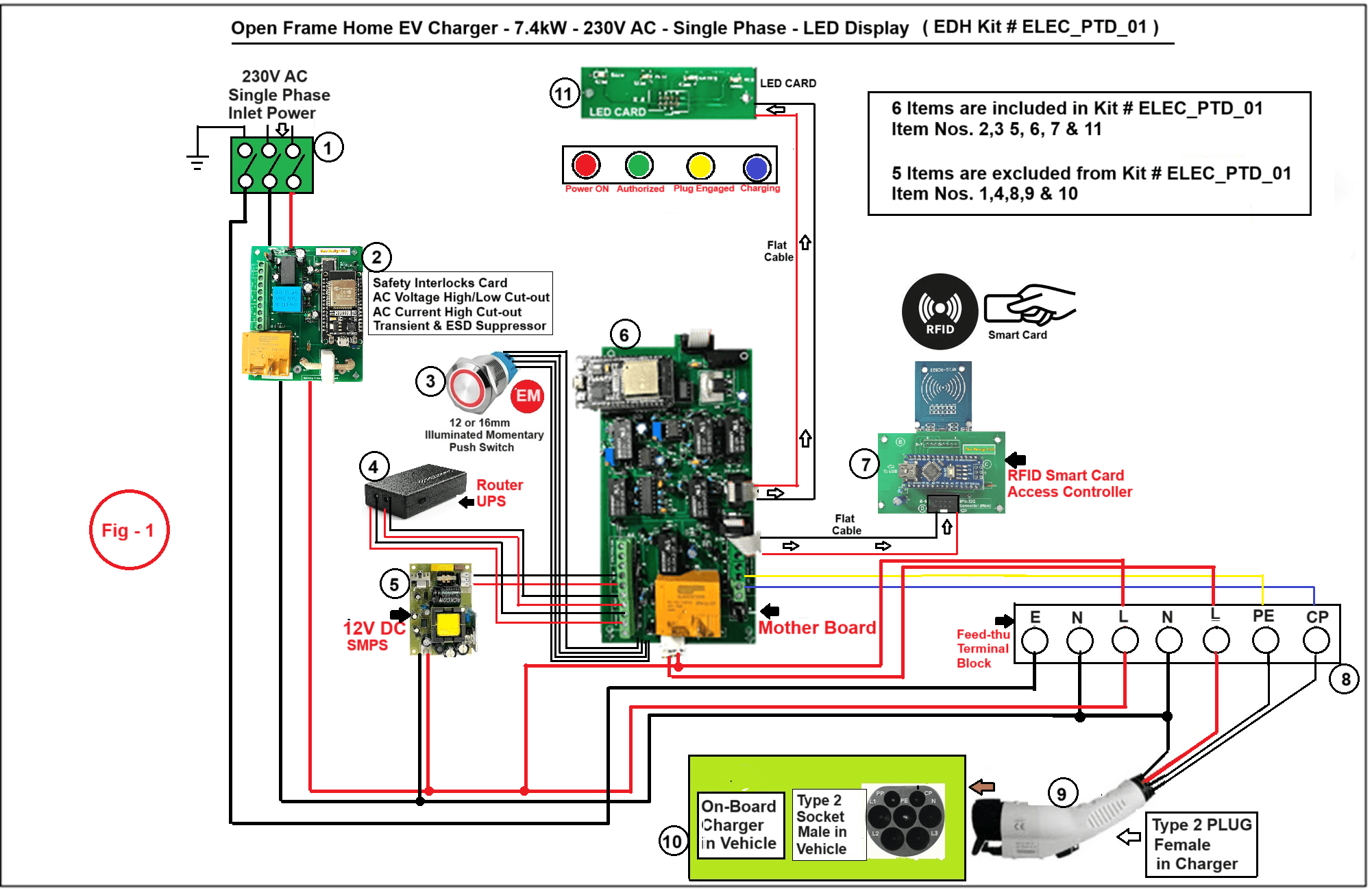
The above Image in Fig – 1 is for :EDH-Kit # Elec_PTD_01:Home EV Charger – 7.4kW-230V AC – Single Phase-LED Display:
This project thesis design kit has 11 Items. We’ll provide 6 Items (Item Nos. 2, 3, 5, 6 , 7 & 11) along with the Kit and balance 5 Items (Item Nos. 1, 4, 8, 9 & 10) are to be procured by you and some of these Items will be avilable in your college lab. However, we’ll provide you sourcing when you’ll buy this Kit.
Here are the Block details:
Block (1): 230V Single Phase AC Power source, which will deliver the required power to operate the Home EV Charger. The Charger has got a capacity of 7.4kW (230V – 32A). The power source should have a capacity of at least 8kW (minimum about 40A) if you want to test the EV Charger in full load.
Block (2) : This is Safety Interlocks Card.
This Card (PCB) is a unique introduction in EV Charger technology. It has all the mandatory interlocks facility.
This Card has a built-in Transient Voltage Suppressor and ESD Protection circuit. It has a Hall Effect based Linear Current Sensor WCS1700 which has a AC Current sensing range of rms 50A. It has a AC Voltage High / Low cut-out facility. The cut-out ranges can be adjusted accurately through computer.
It has a built-in 40A / 240V AC Relay to deliver the AC Charging Power to Electric Vehicle through Type 2 Connector.
Block (3): This is a small (12 or 16mm) Illuminated Momentary Push switch, a bought-out Item. It is used to stop charging in case of emergency. A special circuit is developed in Motherboard to operate this mini Illuminated EM Switch. This will provide a much better aesthetic look of the front facia as the old 25mm Standard Emergency switch looks odd in small enclosure.
Block (4): This is an Optional Item. It is a Mini-UPS which delivers 12V DC to the control circuit only during power failure while charging is on for a minimum time period of 1 Hour.
Block (5): This is a bought-out Item. It is a 12V DC / 1A SMPS which delivers 12V DC to all control circuit of the EV Charger. You may use your lab’s power source.
Block (6): This is an advanced digital control Motherboard which controls the entire charging operation. This is designed and successfully tested at Elec Design Hub Lab and in actual electric vehicle.
It has a 12V DC UPS Control circuit and control circuit for the illuminated emergency switch.
It has a highly precision and stable ESP32 based PWM Pulse Generator. It generates PWM Pulse at a fixed frequency of 1kHz & 53.3% Duty Cycle (which is required for Control Pilot Signal).
Here’s a link through which you will know more about PWM – Pilot Wire Communication: https://elecdesignhub.com/pilot-wire-communication-type2-ev-charger/
It has an advanced and stable Digital Charge Control Circuit which controls the entire charging operations. The Pilot Wire Communication PWM Signal transmitted through “CP” to the Vehicle is converted to DC Control voltages to control Digital Comparators for Charging ‘Start’ & ‘Stop’. It also operates the 40A Charge Control Relay to deliver AC Power to vehicle during charging.
Block (7): The charging process can be accessed either by RFID based Smart Card or by a Bluetooth Controlled Mobile App. Both the Access Control Cards are designed by the Elec Design Hub.
RFID Card will be also used to build to multiply smart Cards.
Block (8): Feed Through Terminal Block – Type 2 Cable of the charger is connected here.
Block (9): This is a bought-out Item. You’ll get complete details when you buy the package. It’s a 32A – 230V AC Single Phase Type 2 (Female) PLUG which has 5 Pins (out of 7 pins) for Single phase operation. When prompted, this Type 2 Plug is to be connected to the Type 2 Socket (Male) at the Vehicle. You may skip this item.
Block (10): On-Board Charger at the Vehicle. Our Kit will have a Simulator PCB to simulate On-Board Charger.
Block (11): This is a small PCB designed by Elec Design Hub. It’s a 4 colour 5mm led charging Status display PCB. It displays: RED: Power ON, Green: Access Granted, Yellow or Amber: Plug Engaged and Blue : Charging in progress.
Interested in your Project Tesis Design Service ? Please fill out the brief form below with as much detail as you can. We’ll get back to you shortly with more information. Thanks for your interest!


